
{{ post.title }}
글 편집
글 편집 (이전 에디터)
{{ post.author.name }}
Posted on
| Version | {{ post.target_version }} | Product |
{{ product.name }}
|
|---|---|---|---|
| Tutorial/Manual | {{ post.manual_title }} | Attached File | {{ post.file.upload_filename }} |
When simulating with RecurDyn, there are cases where the position or orientation of a body suddenly changes, as shown in the video below.
(In the video below, the cylinder on the left and the box at the bottom right are moving to the left at the beginning of the simulation.)
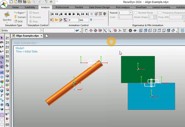
It is because the positions of the Action and Base Markers of the joint are not identical.
When using a joint to connect two bodies in RecurDyn, certain conditions may need to be met depending on the type of joint.
For example, in the case of a Revolute Joint, the positions and the directions of the Z-axes of the Action/Base Markers must align.
In the case of a Fixed Joint, the positions of the Action/Base Markers must identical.
If these conditions are not satisfied, the solver will forcibly adjust the model to meet the conditions before running the simulation.
As a result, the position of the body suddenly changes. (The position of the action body changes so that the Action Marker's position is aligned with the position of the Base Marker.)
The advantage of this feature
Sometimes, when the error is at the level of numerical tolerance, this feature can be very convenient. The solver automatically corrects minor errors and proceeds with the simulation.
When can this feature cause an issue?
However, for example, there are instances where the positions of the Action/Base Markers can be misaligned without the user's awareness.
In such cases, at the beginning of the simulation, you might suddenly notice the body moving to an unexpected position.
It's somewhat better if these changes are visually noticeable, as the user can catch them. However, if the body's position changes without the user's awareness, the intended results may not be achieved.
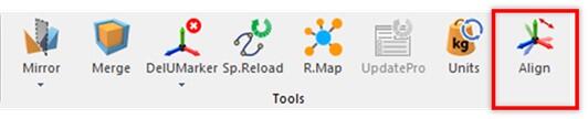
To prevent such cases, starting from RecurDyn 2024, a feature called 'Align Connector' has been added. This feature allows users to verify whether the joints satisfy the conditions before simulation and provides the capability to make adjustments accordingly.
Please refer to the following description for more details.
Align Connectors is a new capability to help you easily verify and modify the differences in terms of the Origin and Orientation of the Action Marker and Base Marker in Joints and Forces.
In the Align Connectors dialog box, a list displays the joints and forces of the subsystem. If the Origin and Orientation are different for the Action Marker and Base Marker, they are highlighted in yellow.
If you select the items you want to change and click the Apply button, the Origin and/or Orientation information (as selected in the Type column) is automatically synchronized, using either a Base to Action or Action to Base method, as selected in the Align column.
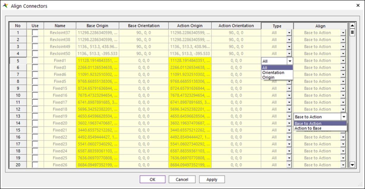
- Type: Choose whether to change both Origin and Orientation or only one of them.
- Align: Choose Base to Action or Action to Base and decide whether to base the final origin and orientation on the Action Marker or Base Marker.
- Joints are supported by the Align Connectors capability: Fixed, Translate, Cylindrical, Screw, Planar, Revolute, Spherical, AtPoint, Orientation
- Forces are supported by the Align Connectors capability: Rotational Spring, Rotational Axial, Bushing
- Additionally, for joints and forces where the Origin and Orientation of the base and action markers do not necessarily match or must be different, or if a Joint or Force lacks a Base Marker and Action Marker, the entity is not displayed in the Align Connector dialog box.