
{{ post.title }}
글 편집
글 편집 (이전 에디터)
{{ post.author.name }}
Posted on
| Version | {{ post.target_version }} | Product |
{{ product.name }}
|
|---|---|---|---|
| Tutorial/Manual | {{ post.manual_title }} | Attached File | {{ post.file.upload_filename }} |
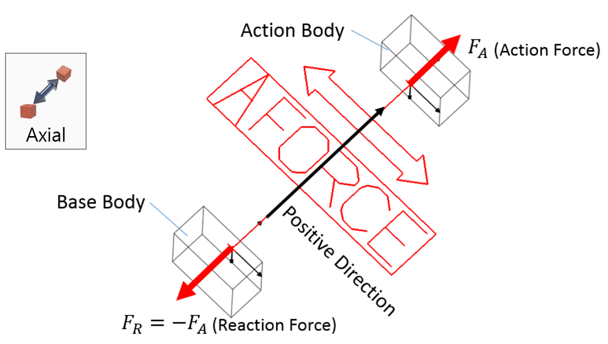
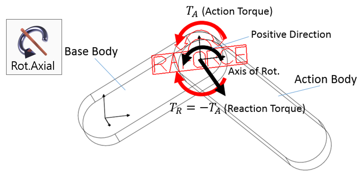
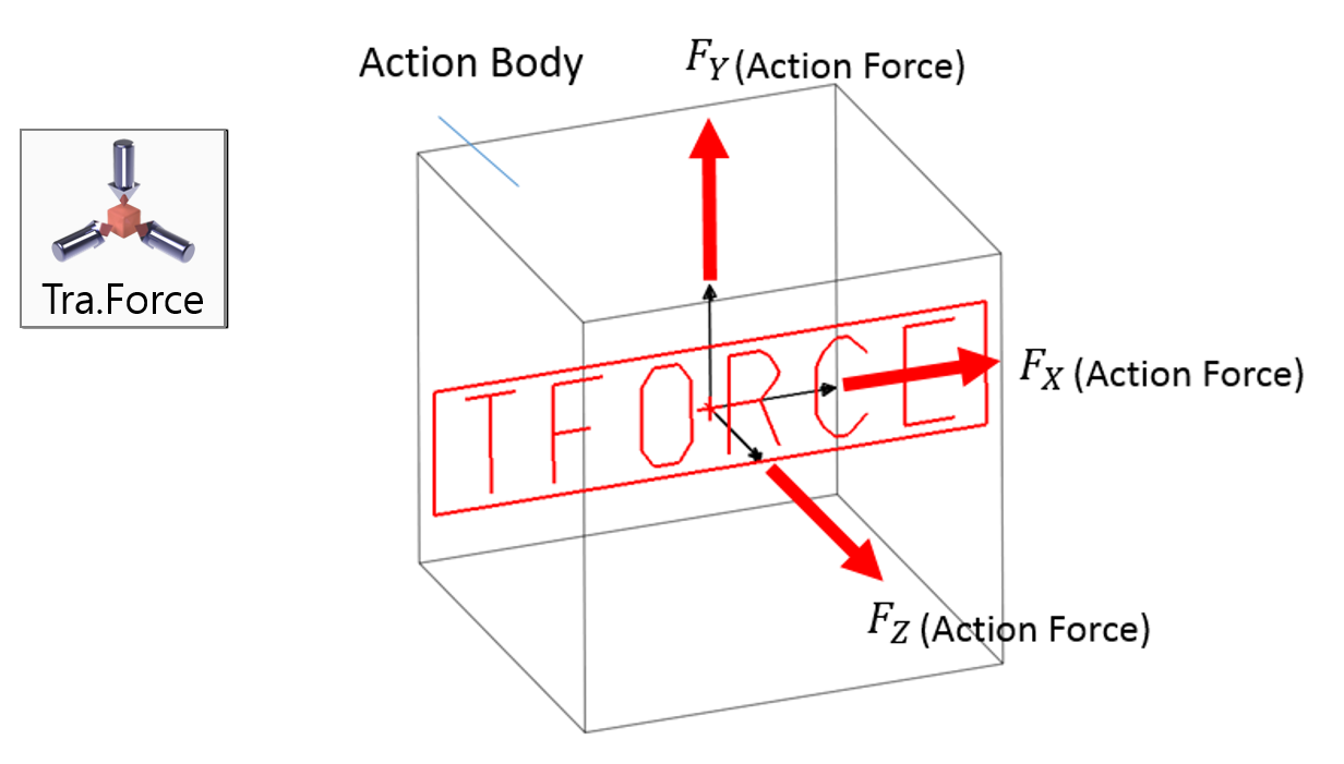
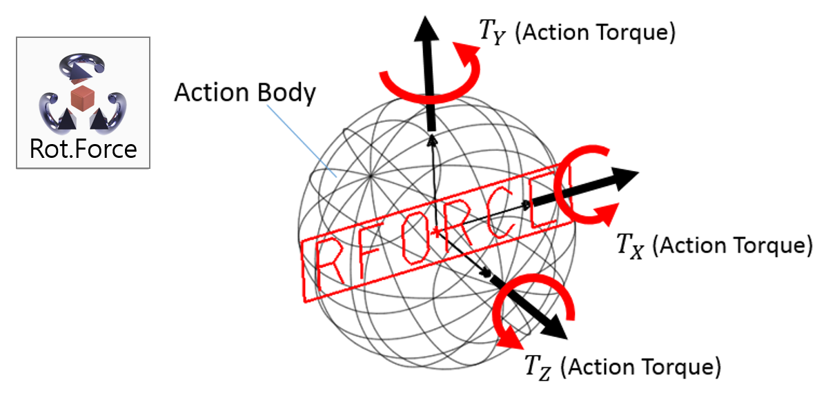
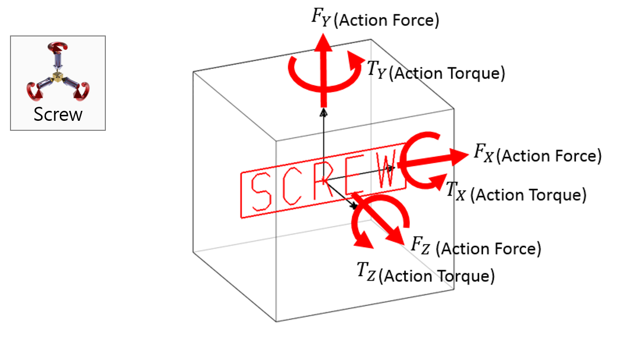
Learn about the various forces and torques supported by RecurDyn, including rotational spring, translational spring, axial forces and others.
The various forces and torques supported by RecurDyn are described here.
Please choose the topic you are interested in from the below list.
Spring and Damper Model
The spring is a mechanical element that can be compressed or extended when an external force is applied and return to its original shape due to its elasticity when the force is removed. Depending on the shape and material, there are various springs such as coil springs, plate springs, spiral torsion springs, rubber springs, air springs, hydraulic springs, etc. Dampers are devices that can absorb vibrational energy. They are also known as vibration isolators or absorbers. As shown below, springs and dampers are used together in suspension systems located between the wheels and vehicle body of an automobile or train to absorb the vibration that comes from the road’s surface and dampen the shock applied to the vehicle body or passengers.

Spring and Damper
(1) Translational Spring and Damper
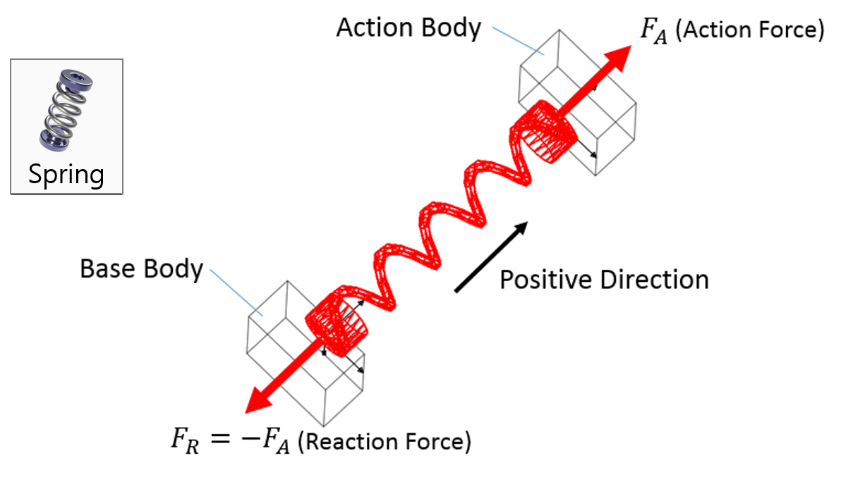
Figure shows the connection between body i and body j that consists of the forces exerted by a translational spring damper. When two bodies connected by a spring move due to an external force, the length of the spring damper changes. At this time, the restoring force that tries to return the spring to its original length and the damping force that dampens the external force are generated due to the elasticity of the spring damper. The restoring force and damping force are in turn applied to the two bodies, causing them to move.
The force of a translational spring damper is calculated as follows using the displacement of the spring as well as the stiffness coefficient and damping coefficient.

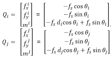
The calculated spring force f_s is applied to bodies i and j as shown in the following figure according to Newton’s law of action-reaction. This spring force is generalized as the forces, Q_i and Q_j, which are used in the equation of motion.

Calculation of translational spring and damper force

Examples of Force in RecurDyn - Axial Force, Translational Spring, and Rotational Spring